Product Description

Â
1.Technical parameters
| Type | Torque | Action Time(S) | Gyration Angle | Motor Power(W) | Rated Current(A) | Weight(Kg) | ||||
| 100 | 100NM | 4/7/15 30/60 |
0-90° 0-360° |
AC220V | DC24V | AC380V | AC220V | DC24V | AC380V | 3.5 |
| 25 | 25 | 15 | 0.32 | 2.03 | 0.1 | |||||
| Power | AC 220V±10% 50HZ/60HZ, AC 380V±10% 50HZ/60HZ, DC24V | |||||||||
| Insulation resistance |  100MΩ/500VDC | |||||||||
| Anti-pressure level | 1500VAC 1Min | |||||||||
| Protection level | IP67(It is no leakage in water about 20 meters deep) | |||||||||
| Limited component | Power-driven: Fully open and close, limit switch. Â Manual: Mechanical stopper |
|||||||||
| Protector | Â Overheat protector(self-recovery) | |||||||||
| Installation position | Â Any direction from 0 to 360 degree | |||||||||
| Electrical connection | M20*1.5 Waterproof cable connection, power wire, signal wire | |||||||||
| Ambient Temp |  -30ºC--60ºC | |||||||||
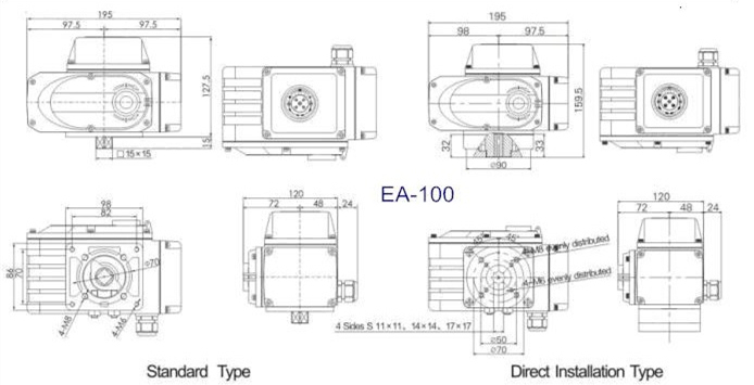
2.Installation Diagram
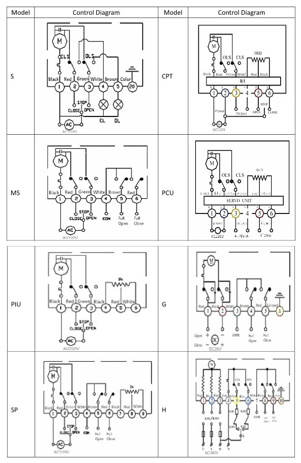
3.Control Diagram
| Model | Circuit | Model | Circuit |
| S | ON/OFF,no output signal | CPT | ON/OFF,output 4~20mA signal |
| MS | ON/OFF,output passive contact signal | PCU | Regulation,output 4~20mA signal |
| PIU | ON/OFF,output 0~1000Ω signal | G | ON/OFF,output passive contact signal |
| SP | ON/OFF,middle position control | H | ON/OFF,output passive contact signa |
Packing&Shipping
1.Packing: inner with bubble wrap,outer with cardboard box and wooden case.
2.Transportation:by sea,by air,by train.
Our Services
1.Professional consultation
2.24 hours response after sale.
3.One year warranty.
4.Safe packing for shipment.
5.Welcome sample order.
Â
Product Description

Â
1.Technical parameters
| Type | Torque | Action Time(S) | Gyration Angle | Motor Power(W) | Rated Current(A) | Weight(Kg) | ||||
| 100 | 100NM | 4/7/15 30/60 |
0-90° 0-360° |
AC220V | DC24V | AC380V | AC220V | DC24V | AC380V | 3.5 |
| 25 | 25 | 15 | 0.32 | 2.03 | 0.1 | |||||
| Power | AC 220V±10% 50HZ/60HZ, AC 380V±10% 50HZ/60HZ, DC24V | |||||||||
| Insulation resistance |  100MΩ/500VDC | |||||||||
| Anti-pressure level | 1500VAC 1Min | |||||||||
| Protection level | IP67(It is no leakage in water about 20 meters deep) | |||||||||
| Limited component | Power-driven: Fully open and close, limit switch. Â Manual: Mechanical stopper |
|||||||||
| Protector | Â Overheat protector(self-recovery) | |||||||||
| Installation position | Â Any direction from 0 to 360 degree | |||||||||
| Electrical connection | M20*1.5 Waterproof cable connection, power wire, signal wire | |||||||||
| Ambient Temp |  -30ºC--60ºC | |||||||||
2.Installation Diagram
3.Control Diagram
| Model | Circuit | Model | Circuit |
| S | ON/OFF,no output signal | CPT | ON/OFF,output 4~20mA signal |
| MS | ON/OFF,output passive contact signal | PCU | Regulation,output 4~20mA signal |
| PIU | ON/OFF,output 0~1000Ω signal | G | ON/OFF,output passive contact signal |
| SP | ON/OFF,middle position control | H | ON/OFF,output passive contact signa |
Packing&Shipping
1.Packing: inner with bubble wrap,outer with cardboard box and wooden case.
2.Transportation:by sea,by air,by train.
Our Services
1.Professional consultation
2.24 hours response after sale.
3.One year warranty.
4.Safe packing for shipment.
5.Welcome sample order.
Â
At present, most of the loaders use gas cap brake system, through the control of the air brake valve to make the Air Brake Booster, Loader Brake Clamp to achieve service braking. Due to the bad operating environment of the loader, frequent forward and backward braking is required in a short period of time, resulting in high failure rate of the pneumatic brake valve. The main fault of pneumatic brake valve is brake failure and leakage. The reason for the fault is that impurities in the air invade the valve body, causing the sealing wear or the spool stuck. In order to avoid the intrusion of impurities and improve the safety, maneuverability and reliability of the pneumatic brake valve, we refer to the existing structure of the pneumatic brake valve to improve its lubrication, sealing and filtration performance. This paper introduces the composition, principle and structure of the improved new pneumatic brake valve.
1. Composition and working principle
(1) Composition
The improved new type of air brake valve is mainly composed of pedal 1, plunger, 2, 3 dust cover, dust scraping oil seal (4), the body 5, and 6 guide ring, rubber spring under 7, 8, 9 valve core, piston return spring 10, the respiration valve 11, last spring 12, gas cavity mesh body under 13, 14, piston seal, valve seal of 14 of 15, vent filter 16, See Figure 1.
(2) Principle
Air brake valve inlet connection gas source, the outlet connection strength pump, when the driver on waste pedal 1, coping under foot pedal lever 2, make the plunger moves down 2, plunger, 2 by rubber spring 7 push the piston moves down 8, 8 piston moves down, the valve core under the 9 and 14 sealing tape from the body, the air inlet and air outlet are linked together, The gas enters the brake afterburner pump to realize braking.
9 when the driver foot pedals, valve core next return spring under the action of upward moves the pistons, 8, 10 to 14 sealing tape sealing valve core is 9 and the lower body, and make the air inlet and air outlet connected to disconnect, when the outlet of the gas through the valve core 9 middle vent discharge into the atmosphere, the piston under the action of 8 spring at last 12, move up, Through the rubber spring 7, the push rod 2 and pedal 1 return to the original position, so as to release the brake.
Air Brake Relay Valve,Sdlg Air Brake Valve,Liugong Air Brake Valve,Xcmg Air Brake Valve,Lonking Air Brake Valve
Henan Hanfeng Construction Machinery Co., LTD , https://www.hf-loaderparts.com