In the application of centrifugal pumps, in order to meet the user's flow requirements and frequency control of the water pump to achieve energy-saving effect, in many occasions, several centrifugal pumps of the same type are used in parallel to meet the requirements in order to achieve the best in parallel pumps. For efficiency, it is necessary to grasp the actual operating point change rule of the parallel operation of the pumps, and it is necessary to know the actual performance curves after several pumps are operated in parallel. At the same time, it can provide detailed and reliable pump parallel operation data for customers and selection units (such as architectural design institutes). It also has very important practical significance. Under normal circumstances, the performance curve of the same type of pumps in parallel is a performance curve of a pump. Based on the above, it is considered that the performances of the two pumps are identical, and the flow shaft power is doubled according to the same head, and the efficiency is not changed. However, this article focuses on the method of testing to obtain the parallel operation performance curve of the same type of centrifugal pump. Parallel operation test 1 Test principle We take two parallel pumps of the same type for parallel operation as an example. For the schematic diagram of the branching test device, please refer to the relevant provisions of GB3216-89 for the installation of the test pipe and its relevant dimensions. The pressure balance point after each pump outlet is seen at the pipe junction point A), that is, when parallel operation, the outflow of the two pumps is mixed at the point A, the pressure is equal. Under normal circumstances, the same model pumps are operated in parallel. The CA and DA sections of the pump outlet pipes are symmetrically arranged. The diameter, length, material, piping accessories and space layout of the pipes used are the same. The resistance coefficient K of the two sections is almost equal. The adjustment valve 9 is a certain degree of opening. At this time, the working conditions of the two pumps are very close. That is, the flow of the two pumps is very close to the equation of the resistance of the pipeline. The hydraulic losses of the CA section and the DA section are the same. Let the pressure at point A be PA, then the pressures at points C and D are all pa-hc, so the numbers of pressure gauges 5 and 6 are the same. This ensures that the two pump outlet pressure is equal to 1,2 bottom valve 3, 4. Vacuum gauge 5, 6 pressure gauge 7, the flowmeter 9 valve through the above analysis shows that in the test process, as long as the valve is adjusted by 9 can guarantee The two pump outlet pressures (pressure gauges 5 and 6 show that Xiangxiang and their respective operating conditions are similar, reaching the basic requirements for parallel operation during the test, at each adjusted operating point, each pump There may be slight differences between suction and speed heads. This is mainly due to the fact that the performance of the two pumps cannot be exactly the same. It is possible to use the average value of the measured heads of each pump at a certain adjusted operating point as the head of the parallel connection. The sum of measured flow is used as the flow in parallel, and the sum of measured power is taken as the power after parallel connection. We have obtained data such as flow, head, and shaft power for parallel operation in each operating condition.
2.2 Test procedure The test of the centrifugal pump shall be started from shutting down the lift, requiring 115% of the flow at the large flow point to be tested below the head (observed in observation table 5 and table 6), and taking more than 13 equal pressure points for each A stable and adjusted operating point, respectively record the flow of each pump Qi and 02, the outlet pressure and H2, inlet pressure H / and H2 ', shaft power Pi and P2, speed cut and m here HiH2H /, Twist is the pressure converted to the reference surface of the pump. 2.3 Processing of test data For each operating point, the average value of the two pump lifts is used as the parallel head: V22VU is the second pump outlet and inlet speed, respectively.
For a stable and adjusted operating point, the total flow in parallel can be calculated by the following formula: To reflect the total power of the two pumps in parallel, each pump power can be added, ie for each specific parallel connection. In fact, the conditions of the two pumps are similar, and the motors used by the two pumps are of the same type, so the average value of “1†and “2†can be used as the collation (1) test of the results of the parallel 3 test. Result All data obtained at the non-predetermined speed in accordance with the conversion of the specified speed shall be based on the specified speed (np), and shall be converted in accordance with the law of proportional flow. 0 Head H The measurement of the power of the P-axis P and the calculated data shall be converted as follows: Head , P is the shaft power after converted speed.
After the parallel connection, the total efficiency Z of the two units is calculated according to the following formula: the performance curve of the parallel operation pump should be used in the form of the flow 0 head H-axis power P and efficiency Z. The curve obtained after the conversion of the data is plotted. At this point, we passed the test. The method has obtained the performance curve of the centrifugal pump set running in parallel. Through the above analysis and discussion, the following conclusions can be drawn: (1) The parallel operation curve obtained by the test method, because the performance difference of each pump of the same model is considered separately. Therefore, it can more objectively reflect the actual situation after the parallel operation of the pumps instead of theoretically based on the performance curve of a single pump. According to the same head, the two pump flow and shaft power are doubled and the efficiency is not changed to synthesize the pumps in parallel operation. Performance curve.
(2) This test method is also applicable to tests in which two or more pumps are operated in parallel.
Plain Trolley introduction
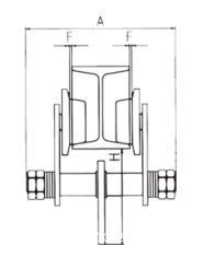
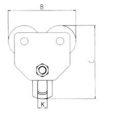
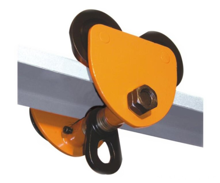
GCT Plain Trolley is a kind of lifting device and it has its own characteristics of simple structure and easy operation. It can be attached to chain hoist of Electric Hoist or any other loading machinery to form a loading trolley. It can be easily running on the botton flange of I beam track at a curve radius for loading and unloading goods and equipments.
By different way of driving , the trolley series can be divided into two types: Geared trolley(GCL) and Plain trolley(GCT). The plain trolley is operated by pushing the load and for the geared trolley, we can pull the hand chain to drive it.
Advantages:
1.Plain trolley series is a kind of lifting device and it has own characteristics of simple structure and easy operation.
2.it can be attached to Chain Hoist or Electric Hoist or any other loading machinery to form a loading trolley.
3.It can be easily running on the bottom flange of beam track at a curve radius for loading and unloading goods and equipment.
4.By different way of driving . the trolley series can be divided into two types: Geared Trolley(GCA)and plain Trolley(GCA) the plain trolley is operated by pushing the load and for the geared trolley. We can pull the hand chain to drive it
Specifications:


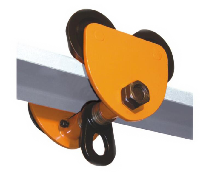
Products show

Additional features and benefits include:
1.Rugged steel side plates formed to include bumpers and trolley guards
2.Frames connected by steel equalizer pin, secured by two nuts on each side
3.Universal tread flanged track wheels equipped with shielded ball bearings
4.Easy rolling on international standard shapes, wide flange shapes or patented rail
5.Hardened wheels and axles for added strength and durability
6.Spacer washers can be shifted inside or outside for easy adjustment to wide range of beams
7.To be used with hook suspended hoist
8.Suspension plate for easy attachment is standard
9.Bearings prepacked with lifetime lubricant
10.One-year warranty
Our Services
1.Client
We treasure and try to understand all the different needs of our clients and seek to forge a long term professional relationship with them. The satisfaction of each and every customer is our main goal and motivation in conducting our business.
2. People
We work as a team and treat each other with respect. Our solid, capable and knowledgeable team is valued as the greatest asset and an integral part of the business.
3. Product
Our products are of HIGH quality standards and always come with certificate of compliance by the manufacturers.
4. Performance
We aim to achieve high level of performance and satisfaction to both our client and people, which include delivering high quality services and treating people with integrity.
5. Free sample and OEM service
We can provide free samples to you and we also have OEM service, we can put your logo on the label and the information you need on the webbing too.

Plain Trolley
Adjustable Plain Trolley,Manual Plain Trolley,Plain Beam Trolley,Plain Push Trolley
Hebei Liston Lifting Rigging Manufacturing Co., Ltd. , https://www.liftingriggingfactory.com