The reverse box has two electromagnetic clutches in the reverse box, which can make the lead roller and the winding roller complete the forward and reverse transmission for the collective production. The device also controls the switch program. During the operation of the equipment, sometimes the yarn pull roller has a momentary pause, and returns to normal in a very short time. There is no breakage phenomenon, but the yarn twist is increased, which seriously affects the product quality. This problem is often caused by the electromagnetic clutch or its poor wiring, and the fault is not easily detected. Sometimes the yarn pull roller does not cause reverse movement when driving, causing driving obstacles, affecting the switch car program, and unable to drive. Since the equipment was put into operation, the collective production operation has not been applied, and the control elements of the collective head device have been modified from the specific conditions of the enterprise. The shaft of the forward and reverse electromagnetic clutch and its carrier coupling part in the reverse box is removed, and the original electromagnetic clutch shaft is replaced by a self-made mechanical shaft. Driven by a drive flange and a helical bevel gear (25T) with a 31T bevel gear mounted on a modified mechanical shaft (the original unit has two 31T conical gears that reversing the yarn take-up axis, now Instead of using a bevel gear, the meshing and winding mechanism are completed. When the machine starts, press the 1/2 button to start the machine at half speed. Press the 1/1 button to start the machine at full speed. The yarn feeding and winding rollers directly enter the forward rotation state. This retrofit simplifies the reverse box drive mechanism, eliminating potential quality hazards and operating in good condition. Shandong Demian Group Demian Co., Ltd. Hou Zhifu Rotor Spinning Machine Exhaust Pipe Reconstruction Hunan Samsung Company has 12 sets of BD200SN rotor spinning machines, and its process exhaust and exhaust exhaust are composed of 3 centrifugal fans ( Among them: 2 sets of T4-72-14 type fan and 1 set of T4-72-12 type fan) are directly drawn through the underground pipeline in series. Its design has the following defects: First, the pipe diameter is large; second, there are many straight bends, resulting in large wind pressure loss. As a result, the process requirements are not met, and the spinning speed can only be opened at a minimum of 31,000 r/min, which limits the increase in production and the quality of the yarn is not high.
After repeated argumentation, we decided to use the three centrifugal fans of the original exhaust system, only to transform the pipeline, and try to reduce the input method to transform. (1) Reconstruction scheme 1 The exhaust pipe is still using the original pipeline, and 12 rotor spinning machines are uniformly extracted by a T4-72-14 centrifugal fan. The centrifugal fan only acts as a relay fan, and its motor power is 18.5. The kW is reduced to 7.5 kW. The process exhaust is additionally equipped with a tapered pipe on the rotor spinning machine to separate the process exhaust from the exhaust. 1#5# rotor spinning machine shares a T4-72-14 fan extraction, 6#12# shares a T4-72-12 fan extraction, and its motor power is reduced from 18.5kW and 28kW to 7.5. kW. (2) Using the effect process, the tail of the windmill is reduced from an average of -274.4Pa to -705.6Pa, and the front of the car is reduced from an average of 0Pa to -264.6Pa, and the platform is basically the same, which solves the problem of large difference. The exhaust tail of the row exhausted from the average -2371.6Pa to -2900.8Pa, the front of the car was reduced from an average of -196Pa to -274.4Pa, and the effect of the exhaust was further improved. The power of three centrifugal fans has been reduced from 65kW to 22.5kW, saving nearly 100,000 yuan in electricity every year. After the transformation, the rotor speed is increased from 31000r/min to 36000r/min, and the output can be increased by about 16. The quality index has obviously improved. We use short-fiber spun C83tex yarn. The ratio of the first and second plates is 1B9. The ratio of the first and second plates is 4B6. The average breaking strength of the single yarn is increased by 7.54cN/tex. To 7.72cN/tex.
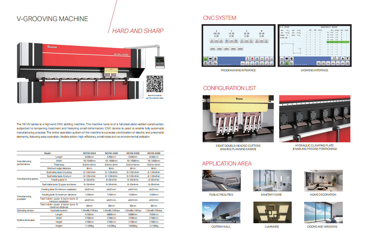
A V-grooving machine is a specialized tool used to create V-shaped grooves or cuts on various materials such as metal, wood, plastic, and even glass. The machine works by using a rotating blade that cuts into the material at a specific angle, creating a V-shaped groove. The depth and width of the groove can be adjusted according to the specific requirements of the project. V-grooving machines are commonly used in industries such as woodworking, metalworking, and signage manufacturing. They are also used in the production of architectural elements such as decorative panels, doors, and windows.

V-Grooving Machine,V-Shape Grooving Machine,High Speed Cnc V-Groove Cutting Machine,High Accuracy V-Grooving Machine
FOSHAN RAGOS NC EQUIPMENT CO.,LTD. , https://www.ragospressbrake.com