With the development of the national economy, especially the implementation of the strategy for the rise of central China, various types of chemical and food enterprises in Wuhan have become more and more numerous. The requirements for the use and calibration of small-caliber vortex flowmeters are also increasing, making small calibers. Measurement has received more and more attention. At present, most of the flow meter verification systems are completed manually, and the flow is calibrated by manually adjusting the gate valves upstream of the standard equipment. There is no visual interface, and the work is laborious and time-consuming. In particular, manual control of the site is extremely noisy for operators. The body causes great harm. The vortex flowmeter automatic verification device based on C++Builder not only solves the above problems well, but also has the advantages of simple hardware connection, easy programming and beautiful operation interface.
C++Builder is an open environment, which makes it very simple to connect with any measurement hardware; it is a graphical programming language, easy to use and easy to learn, and it provides tools to program it over other The language is several times faster; it provides flexible debugging means. It can set breakpoints and set probes to observe changes in data flow during program execution.
Test system design principle
1.1 How Does Quality Law Work?
According to the requirements, the flow meter to be installed is installed in the test pipeline, the water pump is started, the water in the water tank is pumped into the water tower or the high water tank, and when the water starts to overflow, the on-off valve and the regulating valve are opened in turn so that the water passes through the detected vortex. Street flow meters, commutators, and bypass lines flow into the pool. At the beginning of the inspection, after the regulating valve is operated to adjust the flow rate to the required flow rate, the commutator is started to change the water from the bypass line into the weighing container, triggering the timing, and the counting system starts to record the value of the measured flowmeter and the measurement time. When a predetermined amount of water is reached, the commutator is operated so that the water is switched from the weighing vessel to the bypass line, and the flow meter and timer signal recording are stopped at the same time. Compare the weighing value of the electronic scale and the output flow value of the detected flow meter to determine the metering characteristics of the meter being tested. Related Articles Recommendation: Analysis of the accuracy of pressure transmitter verification using calibration devices
1.2 How Does the Standard Table Method Work?
The standard meter part of the standard meter flow standard device can be composed of a single standard table, as shown in Fig. 1, or it can be composed of multiple standard meters in parallel. Its main working principle is to use standard vortex flowmeters (which can be velocity flowmeters, positive displacement flowmeters, critical flowmeters, mass flowmeters, and heat energy meters, etc.) as stan- dards, allowing fluids to pass continuously in the same time interval. The standard flow meter and the checked flow meter compare the output flow values ​​of the two to determine the metering performance of the meter being tested.

Verification system driver and software design
2.1 Drivers
A hardware driver is an application software-to-hardware programming interface that contains operating commands that can be accepted by specific hardware and complete data transfer with the hardware. The VISA function is used when the IPC communicates with the instrument. First, use the VISAOPEN function to open the instrument communication; second, write a certain statement to VISAWRITE controller. After the corresponding operation is completed, the computer reads the data collected by the regulator through the VISAREAD function. After the operation is completed, close the communication with the instrument using the VISA CLOSE function. The driver contains statements that the regulator recognizes. These statements can be found in the regulator's instruction manual. The statement contains the choice of the physical unit of measure, the type, the channel to be closed, digital filtering, and several measurements. Wait. Related articles recommended: Sanchang differential pressure transmitter won reputation for quality and service
2.2 The design of the user interface
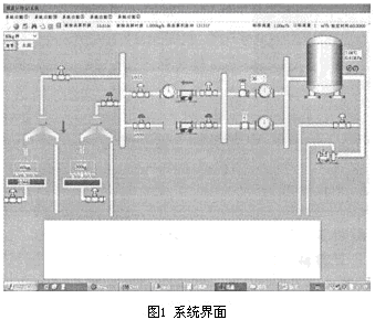
The operator performs the automatic/manual selection of the school point input mode, the automatic/manual opening mode selection, the volume flow meter/mass flow meter selection, and presses the “start detection†button to run the program, that is, the pass through a certain route verification pipeline, according to The checkpoint flow opens the air valve, waits for the flow to stabilize and then measures the pressure, temperature, etc., of the test pipeline in sequence, calculates the standard flow, and measures the flow, and records the obtained data in the flowmeter verification record table. Press the “Verification Result†button to view the verification record; press the “Print Certificate†button to print the certificate; if the pressure is out of range during the verification process, the alarm indicator will immediately change from green to red, alerting the operator to take timely measures. The operation interface is shown in Figure 1.
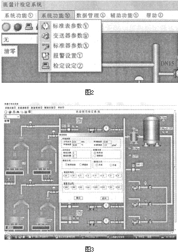
Click on the "System Parameters" menu item, you can see four sub-menu items, the figure as shown in Figure 2.


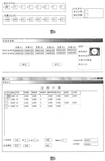
First, enter the number of points to be inspected in the "Checkpoints" input box. The number of white input boxes in the "Checkpoint" input box will be automatically adjusted according to the number of checkpoints entered in the "Checkpoints" input box. Obviously, the "Checkpoint" input box can be accepted between 1 and 8. Then enter the number of times each point is to be tested in the “Checking Times†input box, and the number should be in accordance with the regulations. Finally enter the time for each test execution at each point in the "Authentication Time" input box. In the following figure, enter the subsection flow coefficient of the standard table in the order of flow from the smallest to the largest, and then click “OK†to complete the standard table parameter settings.
Adjust the regulating valve so that the flow reaches the target flow rate and clicks the button. The system enters the verification state, and the point to be checked is popped up. The point after the start is “Startâ€. After the verification time reaches, the dialog box will pop up automatically. If it is the quality method, Then return to the scale to discharge water, otherwise continue to start the next verification. After all the points and times are completed, enter the certificate number, the next verification time, and other data and click "Save". If it is found that the data of a certain traffic point is not good, it needs to be re-verified. Under this traffic, the numbers of input points and times are re-verified, and the new data after verification will be overwritten by the original data.
Verification ends:
To force an end of the quiz, you can select "Check End" or click on the red button shown in the figure. Verification result output print settings, print preview, print. Data printing: The specific process is omitted. Related Articles Recommendation: Capacitive Level Transmitter Signal Conditioning Circuit Design Based on CAV424
2.3 Programming
In the program, automatic/manual measurements were designed to generate reports on the error, repeatability, and uncertainty of each flow point. Standard mass flow, measurement of mass flow calculations, print certificates and alarms.
In summary, based on the data acquisition system and regulators, a vortex flowmeter automatic verification system was established using the C++ BUILDER graphical programming language. The actual use proves that the system has the advantages of less investment, easy operation, and beautiful user interface. It can automatically verify the small-diameter flowmeters such as mass flowmeters and volumetric flowmeters and has high practical value.
Company website
Jump Machinery (Shanghai) Limited is a modern high-tech joint stock enterprise specialized in the turnkey production line of concentrated juice, jam, pulp, tropical fruits, herb and tea beverages, carbonated drinks, wine, beer, yogurt, cheese, milk, butter etc. At the same time, Jump is also committed to manufacturing various food machinery, such as Can Food Machinery , Fruits Juice Machinery, Tomato Sauce Machinery, Fruits Jam Machinery, Dairy Machinery etc.
Jump is able to supply service from A to Z about your project, not only machine manufacturing, installation commissioning, technical training, after-sales service, but also before-sales service, including factory building construction drawings, facilities layout, and water, electricity, boiler steam. Jump has a professional team to help clients to design the layout on worksite and draft the implementation plan, program schedule and expense estimation in each stage of the project until the production line starts the project.
As an industry leader, it has the best projects, professional engineers and technicians, strong R&D department with a number of masters and PhD of food engineering & packaging machinery, stable long-term development and highly rated customer experience in every province in China and also in Africa, the Middle East, Southeast Asia, Oceania, Europe and America.
Apple Juice Production Line,Apple Juice Making Machines,Jucie Making Machinery,Machine To Make Apple Juice
Jump Machinery (Shanghai) Limited , https://www.shanghaimachineries.com