The need to open a pressure relief vent in the protection zone is due to the gas fire extinguishing agent sprayed into the protection zone, which will significantly increase the internal pressure in the protection zone. If there is no proper pressure relief vent, the protection zone of the protection zone may not be able to withstand the increase. The pressure was destroyed. For areas requiring tightness such as constant temperature and humidity, a normally closed pressure relief vent should be provided. Pressure relief vents should be open to more than 2/3 of the net height of the protected area. That is, the pressure relief vent should not be less than 2/3 of the net height of the protected area. The size of the pressure relief port, which is the function of the fire extinguishing agent discharge rate used in the protection zone and the allowable pressure of the enclosure envelope structure to withstand the internal pressure, and the pressure relief port area can be calculated.
working principle
Xian Ruichang Electronics Co., Ltd. pressure relief port is mainly composed of forms, shutters and other components. The pressure relief vent is installed on the external wall of the building and is normally closed. When the fire extinguishing system releases the extinguishing agent, the pressure in the extinguishing area rises. The pressure difference between the inside and the outside of the pressure relief port leaf forms a pressure difference. When a certain value is reached, the window leaf is pushed open. In order to maintain a certain fire extinguishing concentration in the fire extinguishing area and protect the maintenance structure from damage. In accordance with the requirements of the code, pressure relief vents with different pressure relief areas are required for different building spaces. The pressure relief area can be calculated based on the compressive strength of the fire extinguishing area enclosure structure and the injection rate of the extinguishing agent and a specific factor, and the pressure inside and outside the wall can be calculated. The required effective pressure relief area was obtained to meet the engineering needs, thereby ensuring the universality of the company's pressure relief vents.
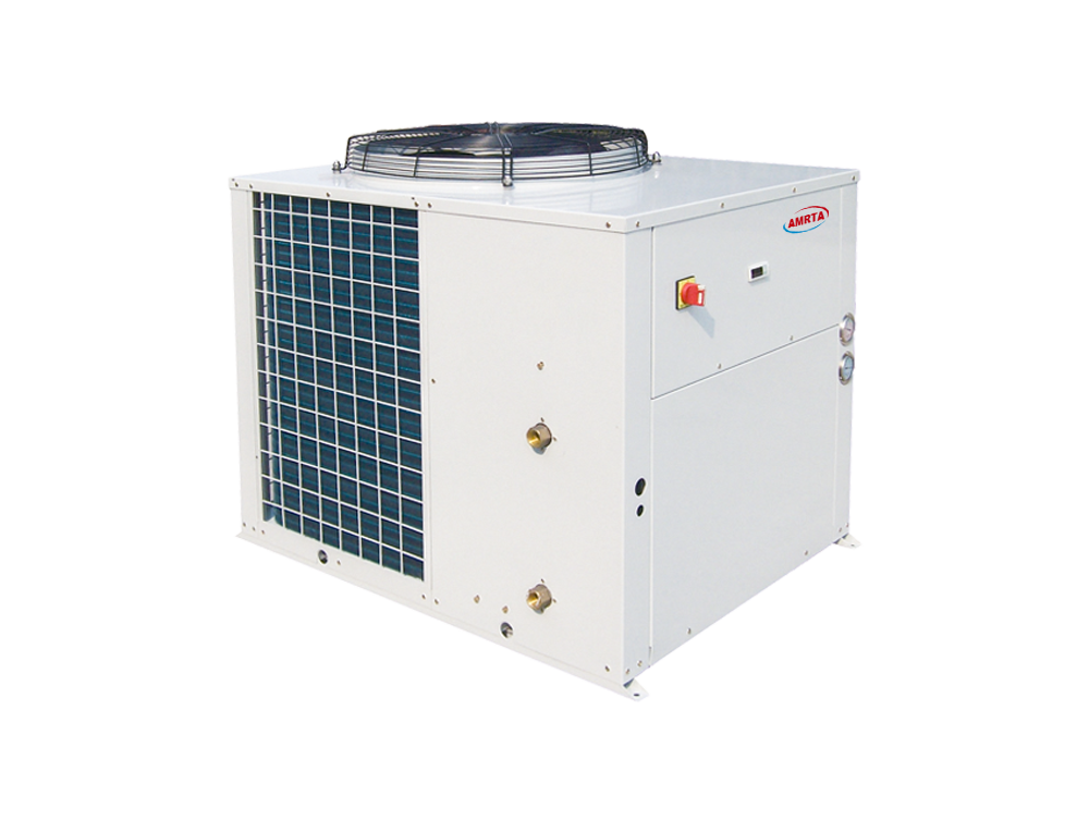
Air Source Heat Pump
Cooling capacity: 20kW-50kW
Characteristics:
1.Structure. Panels and base frame are made from galvanized steel protected with polyester powder painting to ensure total resistance to atmospheric agents.
2.Compressor. Hermetic scroll type compressor, equipped with the crankcase heater and thermal protection with thermal overload cut-out and crankcase heater mounted on rubber vibration isolators.
3.Axial fan. External rotor type axial fans, equipped with single phase direct drive motors, low noise 6 poles, protection level IP54, provided with a protective outlet grille.
4.Evaporator. High efficiency and low pressure drop stainless steel (AISI 316) water exchangers, with anti-freeze heating element (option) and differential pressure switch, factory insulated with flexible close cell material.
5.Condenser. Coils are consisting of seamless copper tubes mechanically expanded into blue hydrophilic aluminum fins, 100% fully quality tested; sub cooling circuit to prevent freezing at the base (optional); protected with metal grill.
6.Desuperheater: High efficiency stainless steel brazed plate heat exchanger, factory insulated with flexible close cell material (optional).
7.Refrigerant circuit. Copper tube connection with charge valve, filter, sight glass, gas-liquid separator, thermostatic expansion valve, low pressure switch with automatic reset, high pressure switch with manual reset. The heat pump unit is completed also with 4-way valve, liquid receiver and one way valve.
8.Water circuit. Built with air vent valve, water drain connection, and female-threaded hydraulic connectors. Water pump (8kW-30kW), differential pressure switch. Expansion tank (8kW-30kW)
9.Electric panel. Consists of:
Compressor contactor
Compressor protection breaker
Fan motor protection breaker
Control circuit protection breaker
Phase sequence relay (only for 3-phase)
Programmable microprocessor controller
10.Optional
Additional electric heater embedded in the coils for defrosting in low temperature ambient. It must be factory installed
Stainless steel covering
Remote condenser
Tube in tube heat exchanger
Water circuit electric heater

Air Source Heat Pump
Air Source Heat Pump,Hot Water Air Source Heat Pump,Heating Air Source Heat Pump,Scroll Air Source Heat Pump
Jinan Amrta Air Conditioning Co.,Ltd , https://www.waterchiller.pl